Wiring Diagram For Current Transformers
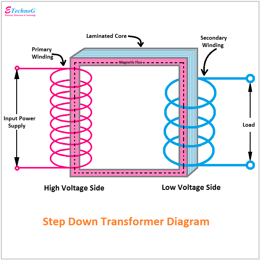
Transformer diagram and constructional parts Transformer explained transformers Transformer constructional
AC Lab - Using a Transformer to Build a 12 VAC Power Supply | AC
Wiring transformer transformers power toroidal 110v phase 220v input diagram winding connections colour series parallel electronics mains two wire colours Three phase transformer connections and basics Transformer wiring diagram explained
0.5 kva transformer primary 240 x 480 secondary 120/240 federal pacific
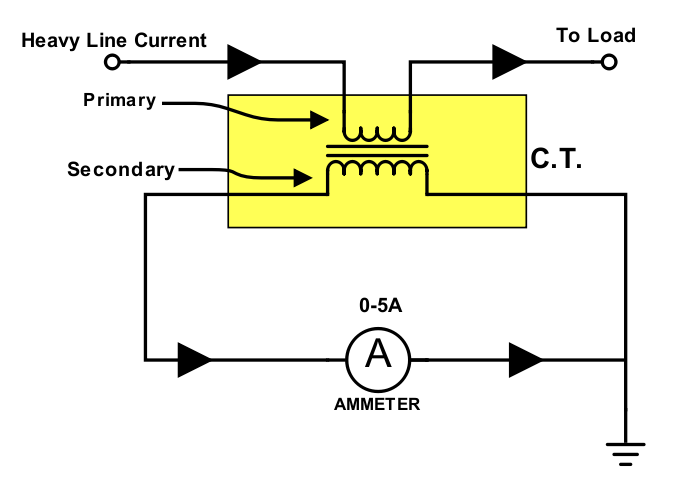
Multi ratio current transformer wiring diagram collectionProper installation of current transformers Transformer diagram wiring current wire tranformer circuitInstallation of current transformers.
Wiring diagram for transformerTransformer current diagram ct circuit principle working construction symbol operating Control transformer wiring diagram power motor electrical diagrams circuits starter 120vTransformer wiring diagram 480 240 480v diagrams volt wire kva phase 120 single federal pacific primary secondary simple low dry.

Current transformer (ct)
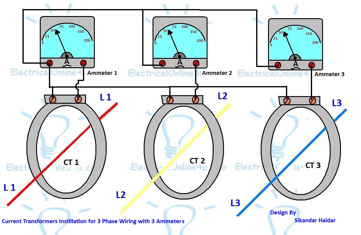
Current wiring ct diagram transformers installation metering connection schematic janitza umg el grounding fig exampleCurrent transformer wiring diagram phase ct meter coil three installation wire ammeter power ampere connection supply meters volt digital system Wiring toroidal mains transformersTransformer phase three connections ratio current star delta audio transformers voltage power auto winding basics configurations turn electrical tutorials diagram.
Transformer current diagram wiring polarity ratio phase ct transformers markings electrical test occasionally misapplied battery been verify factory tests multiWiring of control power transformer for motor control circuits Current transformer installation for three phase power supply- ct coilTransformers installation orientation.
Ac lab
.
.